The modern internet, often conceptualized as a seamless web of interconnected nodes, is actually a fragmented archipelago of private networks. The “End-to-End Principle” a founding principle of internet architecture stating that distinct hosts should communicate directly without intermediate interference has been largely suspended by the widespread deployment of Network Address Translation (NAT). While NAT prevented the premature exhaustion of IPv4 addresses, it introduced significant barriers to bidirectional communication required for peer-to-peer applications like VoIP, online gaming, video conferencing, and decentralized file sharing.
This guide provides a comprehensive technical analysis of NAT traversal mechanisms the techniques developed to restore direct connectivity between devices hidden behind NATs and firewalls.
Summary
What is NAT Traversal?
- NAT (Network Address Translation) allows multiple devices to share a single public IP address but breaks direct peer-to-peer connectivity.
- NAT traversal is a collection of techniques to establish direct connections between devices behind NATs.
Key Protocols:
Core Techniques:
- UDP Hole Punching: Both peers send packets simultaneously to “punch holes” through their NATs.
- TCP Simultaneous Open: Similar technique for TCP connections using the SO_REUSEADDR socket option.
- Birthday Attack: Uses probability to find matching ports when behind hard NATs.
NAT Types:
- Endpoint-Independent Mapping (Easy NAT): Same external port for all destinations traversal works well.
- Endpoint-Dependent Mapping (Hard NAT): Different ports per destination requires advanced techniques or relay fallback.
Tools and Solutions:
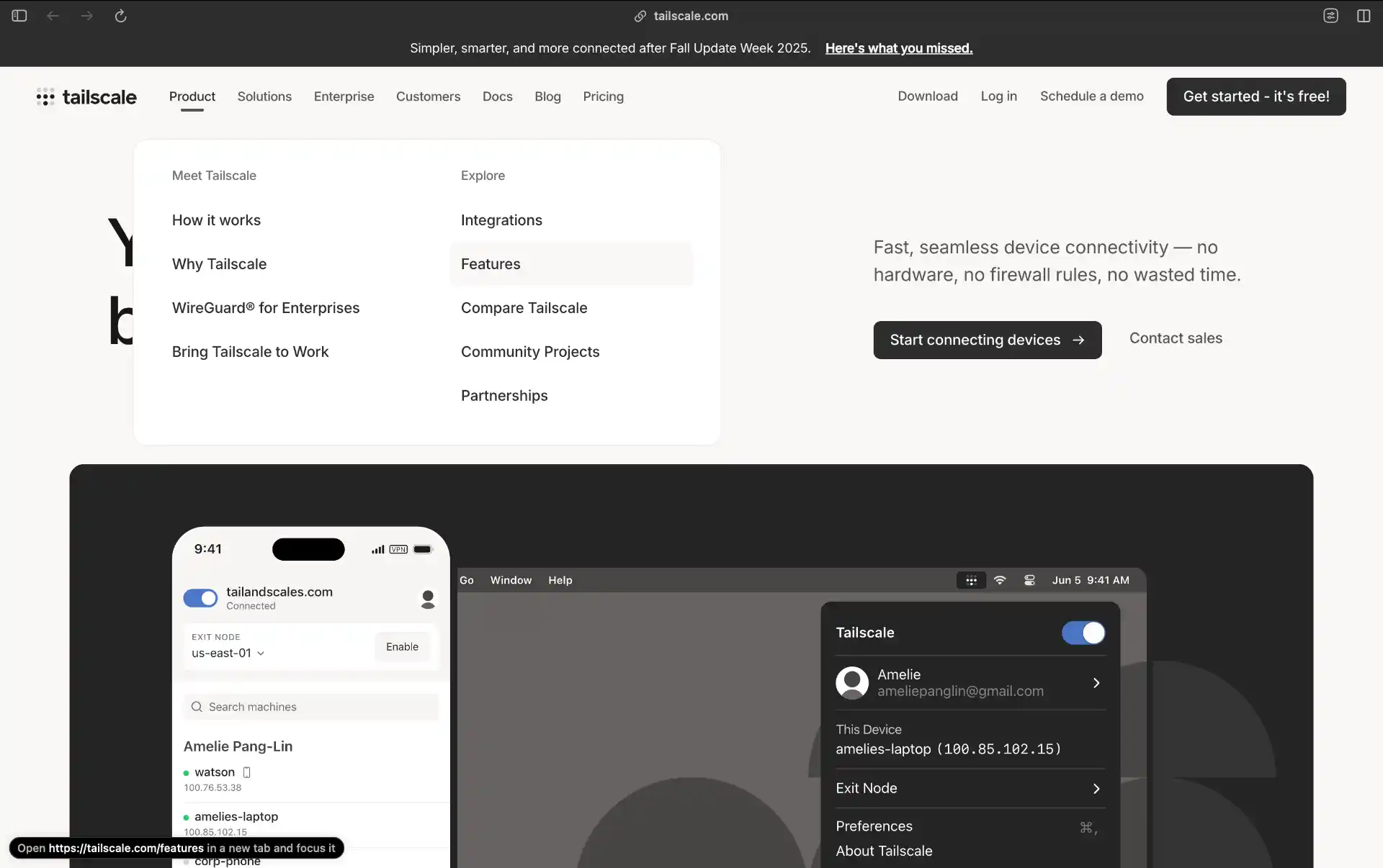
- Tailscale: Uses WireGuard with sophisticated NAT traversal.
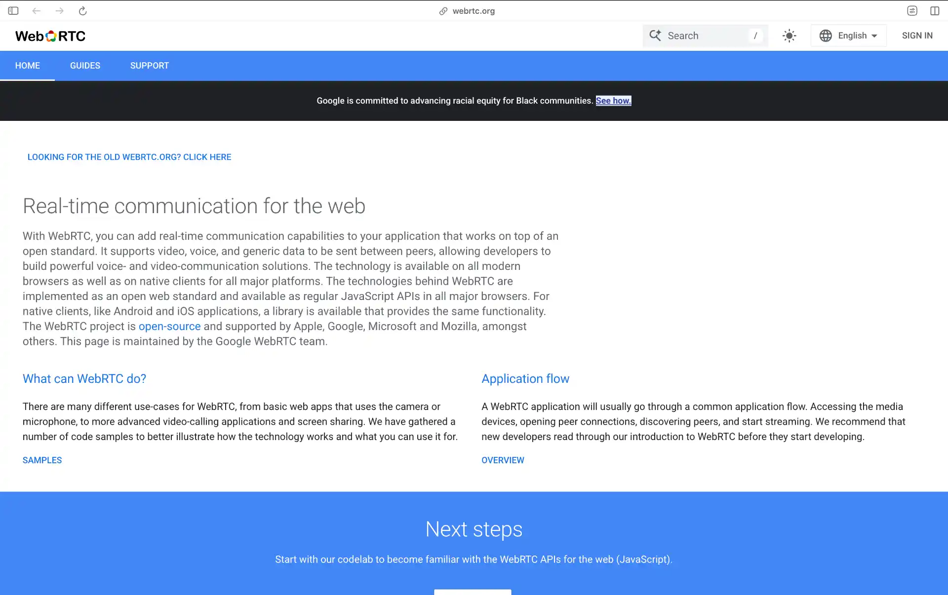
- WebRTC: Built-in NAT traversal for browser-based peer-to-peer.
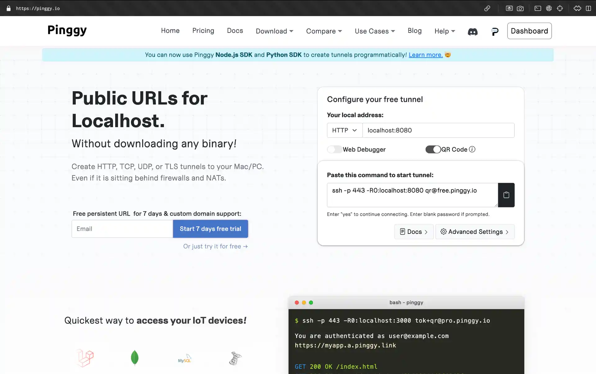
- Pinggy: Simple tunneling solution that bypasses NAT entirely.
Why Does NAT Exist?
In the early internet, every connected device had a globally unique IP address. The 32-bit address space of IPv4 provides roughly 4.3 billion unique addresses which seemed sufficient in the 1980s but quickly became inadequate as the internet exploded in popularity.
RFC 1631 proposed NAT as a solution: allow entire local networks to sit behind a single public IP address, multiplexing traffic based on port numbers. Private address ranges (10.0.0.0/8, 172.16.0.0/12, 192.168.0.0/16) defined in RFC 1918 were reserved for internal use. This was intended as a temporary stopgap until IPv6 deployment, but it became the permanent infrastructure of the IPv4 internet.
The Problem: Broken End-to-End Connectivity
NAT created a fundamental dichotomy in the network:
The Public Realm consists of devices with globally routable IP addresses like servers and gateways. The Private Realm contains devices with non-routable addresses that exist behind NAT devices.
Traffic flows easily from private to public (the classic client-server model). The NAT tracks outbound requests and routes replies back correctly. However, traffic cannot flow from public to private without a pre-existing state entry. An unsolicited packet arriving at a NAT’s public interface is dropped because the NAT doesn’t know which internal host should receive it.
This effectively renders private hosts invisible to the public internet, breaking the fundamental assumption of peer-to-peer connectivity where every participant acts as both client and server.
Understanding How NAT Devices Work
To traverse a NAT, you must first understand its internal logic. A NAT device is not merely a router it’s a packet rewriter and a stateful firewall.
The Translation Table and 5-Tuple
The core of any NAT device is the Translation Table. When a packet traverses from LAN to WAN, the NAT modifies the IP and TCP/UDP headers, tracking these modifications using a “5-tuple” identifier:
- Source IP
- Source Port
- Destination IP
- Destination Port
- Transport Protocol (TCP/UDP)
For example, when a host at 192.168.1.5:5000 sends a packet to a web server at 203.0.113.80:80, the NAT allocates an external port (e.g., 198.51.100.1:25000) and creates a mapping:
{192.168.1.5:5000 <-> 198.51.100.1:25000}
All return traffic matching this mapping gets translated back and forwarded to the internal host.
Stateful Firewalling and Solicitation
Most NATs integrate stateful packet inspection (SPI), operating on the principle of solicitation:
Solicited Traffic is inbound traffic matching an active flow initiated from inside the network like a web server response to your browser’s request. The firewall permits this because it sees a corresponding entry in its state table.
Unsolicited Traffic is inbound traffic with no matching state table entry. The default security policy for almost all consumer and enterprise NATs is to DROP unsolicited inbound traffic.
NAT traversal via “hole punching” is the art of converting what appears to be unsolicited traffic into solicited traffic. By inducing the internal client to send a packet to a peer, the client forces the NAT to create a state entry. When the peer replies, the firewall treats the incoming packet as a response and permits it.
Classifying NAT Behavior: Easy vs Hard NATs
The success of traversal depends entirely on the NAT device’s behavior. Modern engineering uses the taxonomies defined in RFC 4787.
Mapping Behavior
Endpoint-Independent Mapping (EIM): The NAT uses the same external port for all packets from a specific internal IP:port, regardless of destination. This is the “easy” NAT that allows successful peer-to-peer connectivity because peers can discover and share their external addresses.
Endpoint-Dependent Mapping (EDM): The NAT assigns a different external port for every different destination. This is the “hard” NAT (also called Symmetric NAT) that breaks standard hole punching. If you connect to STUN server S and get Port A, then connect to Peer B, the NAT assigns Port B. Peer B sends traffic to Port A (learned via signaling), but the NAT expects traffic on Port A only from Server S. Connection fails.
Filtering Behavior
Endpoint-Independent Filtering: Allows packets from any source if a mapping exists (Full Cone NAT).
Address-Dependent Filtering: Only allows packets if the source IP matches a previous destination.
Address and Port-Dependent Filtering: Only allows packets if both source IP and port match a previous destination (Port Restricted Cone NAT).
For successful traversal without a relay, you need Endpoint-Independent Mapping combined with any filtering behavior that can be overcome by hole punching.
The Mechanics of Hole Punching
Hole punching is the primary mechanism for bypassing restricted NATs. It exploits the gap between mapping logic and firewall logic.
UDP Hole Punching: The Sequence
The goal is to establish bidirectional flow state in two firewalls that default to blocking inbound traffic.
The Setup:
- Peer A (Internal:
10.0.0.1:5000) is behind NAT A - Peer B (Internal:
192.168.1.5:6000) is behind NAT B - STUN Server S (Public:
203.0.113.50:3478)
Phase 1: Discovery
Peer A sends a UDP packet to Server S
- NAT A allocates Public Port
10000 - Server S sees the request from
203.0.113.1:10000
Peer B sends a UDP packet to Server S
- NAT B allocates Public Port
20000 - Server S sees the request from
198.51.100.2:20000
Phase 2: Signaling
Peers exchange their public coordinates via an out-of-band signaling channel (WebSocket, SIP server, or coordination server). Peer A now knows to target 198.51.100.2:20000. Peer B knows to target 203.0.113.1:10000.
Phase 3: The Punch (Simultaneous Send)
Peer A sends UDP to 198.51.100.2:20000
- NAT A creates state: “Allow inbound from
198.51.100.2:20000” - NAT B drops the packet (no matching state yet)
Simultaneously, Peer B sends UDP to 203.0.113.1:10000
- NAT B creates state: “Allow inbound from
203.0.113.1:10000” - NAT A accepts the packet (matches the state from step 1)
Connection established! Both NATs now have bidirectional state entries.
The key insight is that packets don’t need to be related — they just need to create the right firewall state entries.
TCP Hole Punching: Simultaneous Open
TCP hole punching is trickier because TCP is connection-oriented. Standard TCP uses a three-way handshake (SYN → SYN-ACK → ACK), but both P2P peers act as clients sending SYN packets.
TCP hole punching relies on a specialized state transition called Simultaneous Open:
- Standard: CLOSED → SYN-SENT → ESTABLISHED
- Simultaneous Open: CLOSED → SYN-SENT → SYN-RECEIVED → ESTABLISHED
Peers must set the SO_REUSEADDR flag on their sockets to bind and connect from the same local port. When both send SYN packets simultaneously, each NAT creates state for the outgoing SYN. When the crossing SYN arrives, it matches the existing state.
TCP hole punching has a lower success rate (~64%) compared to UDP (~82-95%) because some firewalls strictly enforce client-server TCP semantics and reject incoming SYN packets on connections in SYN-SENT state.
The Hairpinning Problem
A distinct failure mode occurs when two peers are behind the same NAT but try to connect via their public IPs. The packet travels to the router’s WAN interface, and the router must recognize that the destination is its own WAN IP, translate it back to the internal peer, and route it out the LAN interface.
This “U-turn” is called hairpinning or NAT loopback. Many older or carrier-supplied routers lack this capability they treat such packets as invalid and drop them.
This is why
ICE ensures that local “Host” candidates are tried first, bypassing the NAT entirely for local peers.
Protocol Deep Dive: STUN (RFC 5389)
Session Traversal Utilities for NAT (STUN) is the protocol that facilitates the discovery phase of hole punching. It allows a client to answer three questions: “What is my public IP?”, “What is my public port?”, and “Is the NAT well-behaved?”
STUN is a lightweight binary client-server protocol running typically on UDP port 3478. The client sends a “Binding Request” and receives a “Binding Response” containing its public IP:port as seen by the server.
Key Attributes:
- MAPPED-ADDRESS: Returns the client’s public IP:port
- XOR-MAPPED-ADDRESS: The IP is XORed with the transaction ID to prevent broken Application Layer Gateways (ALGs) from tampering with the payload
Beyond discovery, STUN is vital for keeping holes open. NAT state tables have expiration timers for UDP, this timeout can be as short as 30 seconds. STUN “Binding Indications” serve as keepalive packets to reset these timers.
Limitation: STUN only provides information it doesn’t relay data. If the NAT uses Endpoint-Dependent Mapping, the IP:port learned via STUN will differ from the one assigned for the P2P connection, making STUN data useless for direct connectivity.
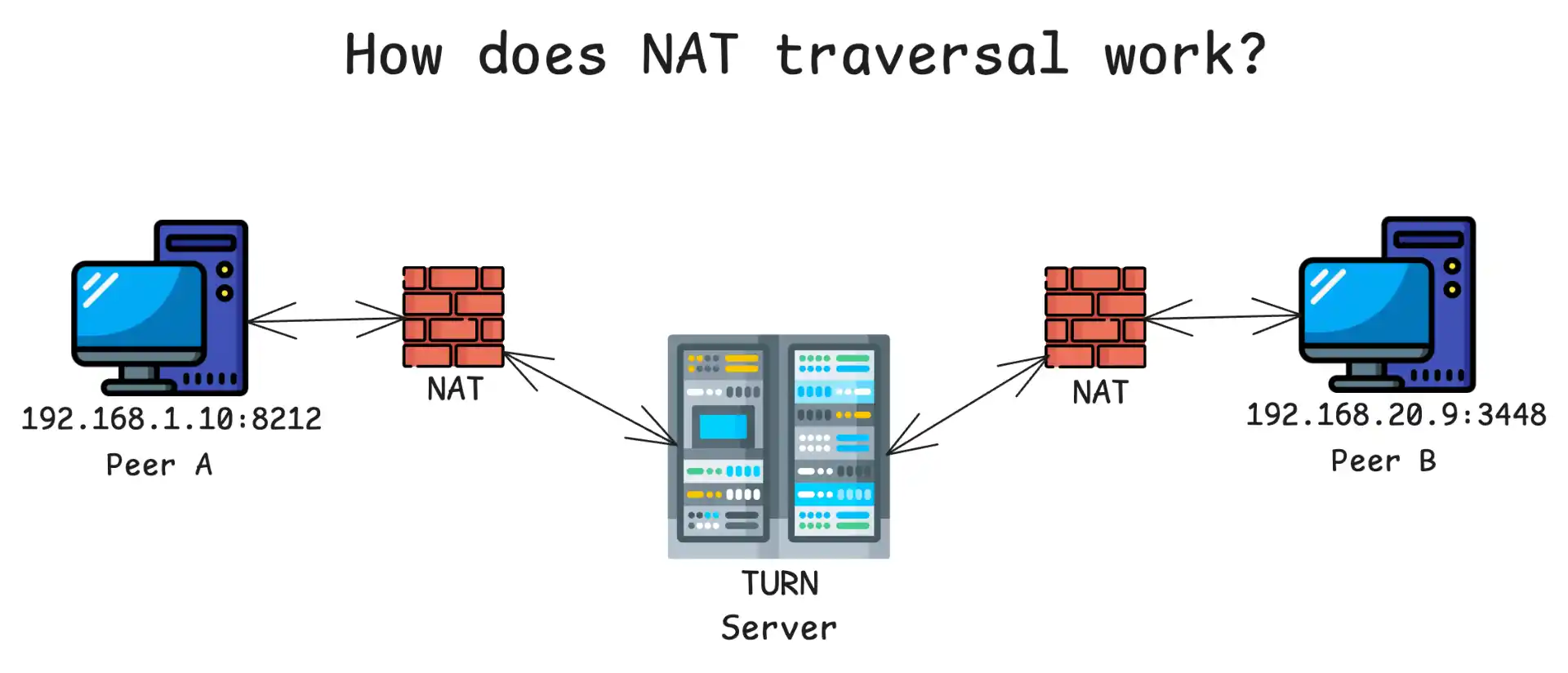
Protocol Deep Dive: TURN (RFC 5766)
Traversal Using Relays around NAT (TURN) is the fallback when direct hole punching fails. Unlike STUN, TURN actually relays data.
How it works:
- Client requests an Allocation from the TURN server
- Server grants a public relay address (e.g.,
203.0.113.5:45000) - Client shares this relay address with its peer
- All traffic flows through the TURN server
The Permission System: To prevent abuse as an open proxy, TURN implements strict permissions. The client must explicitly authorize each peer IP that can send data to its relay allocation.
Data Modes:
- Send/Data Indications: Wraps payload in TURN headers (36 bytes overhead per packet)
- Channels: Binds a 4-byte channel number to a peer for high-volume streams, reducing overhead
TURN adds latency (triangulation delay) and bandwidth costs. In typical WebRTC deployments, TURN is required for approximately 10-15% of connections, mostly on cellular networks and restrictive enterprise Wi-Fi.
ICE: The Brain of NAT Traversal (RFC 8445)
If STUN and TURN are tools, Interactive Connectivity Establishment (ICE) is the foreman. It’s a framework that unifies these protocols to find the best possible path between peers.
The algorithm is elegantly simple: try everything at once, and pick the best thing that works.
Candidate Gathering
The ICE agent gathers “candidates” — potential addresses where it can receive traffic:
Host Candidate: Physical interface IP (e.g., 192.168.1.5). Lowest latency, free. Used for local peers.
Server Reflexive Candidate (srflx): Public IP derived from STUN. Used for P2P over the internet.
Relayed Candidate (relay): Address allocated by TURN. High latency, high cost. Fallback only.
Peer Reflexive Candidate (prflx): Address discovered during connectivity checks (if NAT changes port mid-session).
ICE sorts candidates using this formula from RFC 8445:
Priority = (2^24 × TypePreference) + (2^8 × LocalPreference) + (256 - ComponentID)
TypePreference values ensure the ordering: Host (126) > Peer Reflexive (110) > Server Reflexive (100) > Relay (0).
This guarantees that if a direct Host-to-Host path exists (peers on same LAN), it’s tried first. If that fails, srflx-to-srflx (hole punching) is tried. Finally, relay-to-relay is the last resort.
Connectivity Checks
ICE pairs local candidates with remote candidates and sends STUN Binding Requests as probes. These packets serve dual purposes: opening firewall holes AND verifying path connectivity. After some time, ICE picks the “best” working path based on latency or priority.
Explicit Port Mapping Protocols
While STUN and TURN work around NATs, explicit control protocols let applications formally request port mappings.
UPnP IGD (Universal Plug and Play Internet Gateway Device): Uses XML/SOAP over HTTP to request mappings like “map external port 8080 to my internal port 80.” Security concern: typically lacks authentication, allowing malware to open firewall holes.
NAT-PMP and PCP (Port Control Protocol): Apple’s NAT-PMP evolved into IETF’s PCP (RFC 6887). Designed for carrier-grade NAT with authentication mechanisms, though consumer router support remains sparse.
The CGNAT Challenge
The exhaustion of IPv4 forced ISPs to adopt Carrier-Grade NAT (CGNAT), inserting a NAT device within the ISP’s own network. This creates “Double NAT” scenarios:
User Device → Home Router NAT → ISP Network (100.64.x.x) → CGNAT → Public Internet
RFC 6598 reserved the 100.64.0.0/10 “Shared Address Space” for CGNAT to prevent conflicts with user networks.
Implications: Users cannot use UPnP or manual port forwarding because their home router is itself behind the carrier NAT. Hole punching only works if the CGNAT supports Endpoint Independent Mapping and hairpinning and hairpinning within CGNAT is often broken due to routing complexity.
IPv6: The Ultimate Solution (Eventually)
IPv6 provides a virtually infinite address space, theoretically eliminating the need for NAT. Every device can have a globally routable address.
However, stateful firewalls still exist in IPv6 networks. You still need firewall traversal techniques, but can eliminate STUN, birthday attacks, port mapping protocols, and hairpinning complexity.
The challenge: we’re only at about 40% IPv6 adoption globally, unevenly distributed. NAT64 devices bridge IPv6-only networks to the IPv4 internet, introducing yet another traversal scenario.
Practical Implementation Checklist
If you’re implementing NAT traversal, here’s what you need:
Prerequisites:
- A UDP-based protocol (TCP traversal is much harder)
- Direct socket access in your program
- A communication side channel with peers
- STUN servers for address discovery
- Fallback relay network (highly recommended)
Implementation Steps:
- Enumerate all ip:ports on directly connected interfaces
- Query STUN servers to discover WAN ip:ports and NAT behavior
- Try port mapping protocols (UPnP, NAT-PMP, PCP) for additional WAN ip:ports
- Check for NAT64 and discover WAN ip:port through that if applicable
- Exchange all ip:ports with peers via your signaling channel, along with cryptographic keys
- Optionally, begin communicating through fallback relays immediately for quick connection establishment
- Probe all peer ip:ports for connectivity; use birthday attack techniques for hard NATs if needed
- Upgrade transparently to better paths as they’re discovered
- Downgrade to maintained paths if active path fails
- Ensure end-to-end encryption and authentication
Several production-ready solutions handle NAT traversal complexity:
Tailscale: Uses WireGuard with sophisticated NAT traversal including STUN, hole punching, and their DERP relay network. Provides seamless mesh networking.
WebRTC: Built into browsers with full ICE implementation. Great for audio, video, and data channels in web applications.
Pinggy: Takes a different approachinstead of traversing NAT, it creates secure tunnels that bypass NAT entirely. Useful for exposing local services without configuring routers.
ZeroTier: Software-defined networking with built-in NAT traversal for creating virtual LANs across the internet.
Conclusion
NAT traversal is a complex solution to a problem that was never supposed to exist. It’s friction caused by the persistence of IPv4 in a world that has outgrown it. Through the ingenious application of hole punching, the coordination of ICE, and the fallback capabilities of TURN, applications maintain the user experience of seamless connectivity despite the underlying fragmentation.
While IPv6 promises to restore the End-to-End principle, the transition is generational. Until IPv6 is ubiquitous, NATs residential, enterprise, and carrier-grade will remain the gatekeepers of the internet, and the machinery of traversal described here will remain the essential key to opening those gates.
The illusion of a connected world is maintained not by open doors, but by the relentless, automated knocking of traversal protocols.